Pneumatic Module
Parts
- 1 1032to18Tube
- 1 1032to18TubeTee
- 1 14NPT20psiPRV
- 1 14NPTnipple
- 1 14NPTtee
- 1 14NylonPushTee
- 2 AFL Pneumatic System Frame
- 4 AirRegulator
- 1 DispenseController
- 1 ETFETube18OD
- 2 FiveWayValve
- 3 M3 nuts
- 3 M3x35 screws
- 8 M4x10 screws
- 4 NylonTube14OD
- 13 PushConnector14NPTto14Tube
- 6 PushConnector14NPTto18Tube
- 1 PushConnector14NPTtoTee14Tube
- 1 PushConnector14NPTtoTee18Tube
- 2 PushConnectTee14
- 1 RJ45 jack
- 1 SystemEnableValve
- 2 TefzelTube18OD
Tools
The role of the pneumatic module is multi-fold:
- provide switched, high pressure (60-80 psig) nitrogen/air to the loader actuator in the robot
- provide a series of streams of reduced pressure nitrogen to dispensing components: (15-20 psig to dispense bottles, 15-30 psig to electronic dispense regulator), including safety features like pressure relief valves
- (in revision 2 and greater) house the electronic dispense regulator
It is worth noting that a number of configuration changes can be made in the pneumatic module to adapt the robot to locally available utilities; for instance, sometimes facilities have high-pressure filtered clean dry air available but nitrogen is only available at lower pressure. In this case one can supply the actuator with air and the dispense system with nitrogen.
Materials: AFL Pneumatic System Frame FiveWayValve AirRegulator PushConnector14NPTto14Tube PushConnector14NPTto18Tube PushConnectTee14 NylonTube14OD ETFETube18OD M4x10 screws No. 2 Phillips screwdriver RJ45 jack
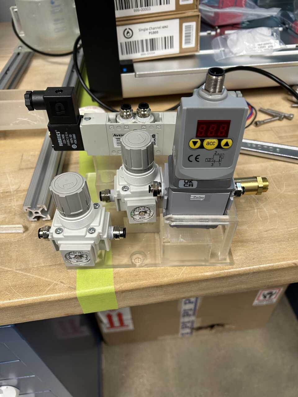
Step 1: Assemble the frame and main components
-
3D print the AFL Pneumatic System Frame if not already available.
-
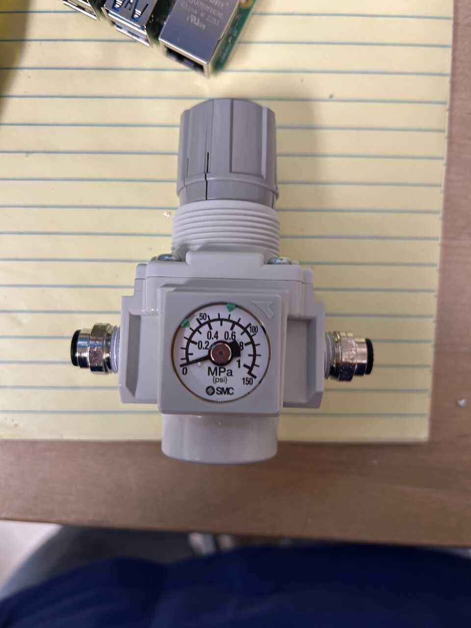
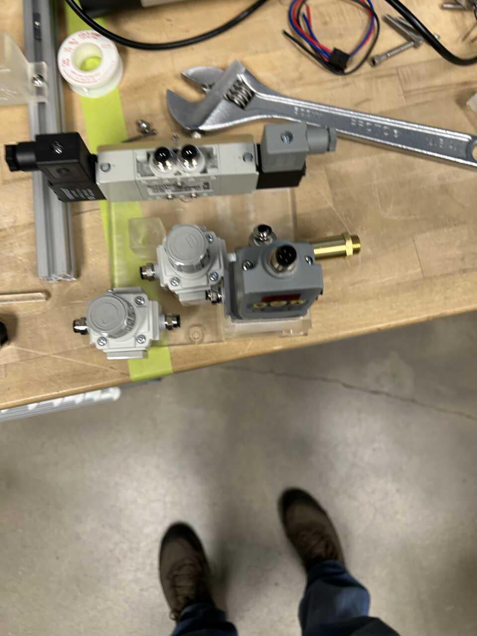
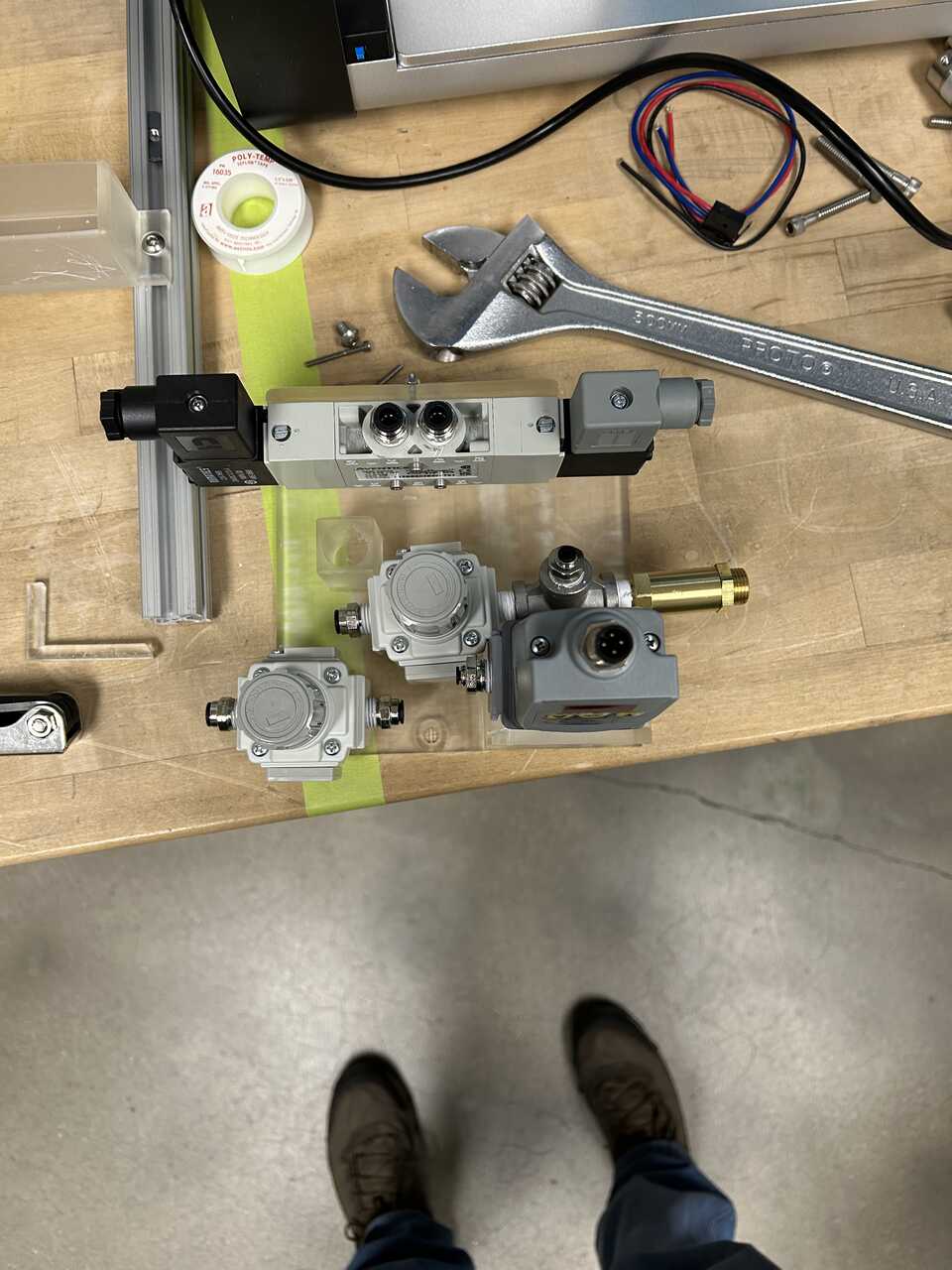
Setup the valves and regulators with fittings.
-
FiveWayValve On the valve, install PushConnector14NPTto14Tube on ports marked 1, 2, and 4.
- AirRegulator:
- On the first regulator (actuator), install a PushConnector14NPTtoTee14Tube on the inlet side and a PushConnector14NPTto14Tube on the outlet side.
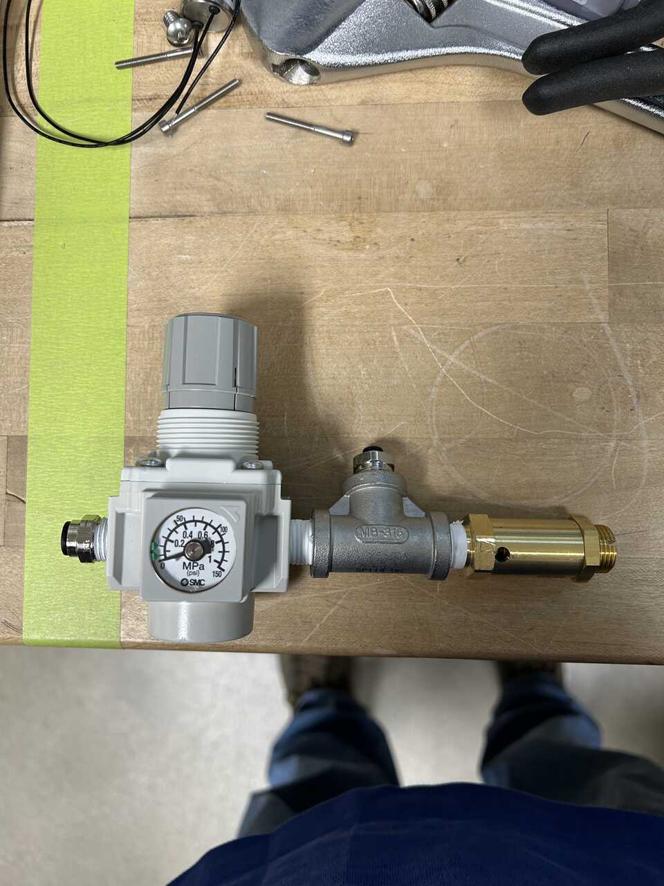
 - On the other regulator (dispense), install a [PushConnector14NPTto14Tube]{: Class="missing"} on the inlet side and a
 [14NPTnipple]{: Class="missing"}, [14NPTtee]{: Class="missing"}, [14NPT20psiPRV]{: Class="missing"}, and [PushConnector14NPTtoTee18Tube]{: Class="missing"} on the outlet side.
 - DispenseController install a PushConnector14NPTto18Tube on the inlet side and a PushConnector14NPTto18Tube on the outlet side.
- SystemEnableValve, install a 1032to18Tube fitting on one side, and a 1032to18TubeTee fitting on the other side.
- DispenseController install a PushConnector14NPTto18Tube on the inlet side and a PushConnector14NPTto18Tube on the outlet side.
- SystemEnableValve, install a 1032to18Tube fitting on one side, and a 1032to18TubeTee fitting on the other side.
-
Flip the regulator dials:
- rotate the covering on the face with the dial in the direction indicated by the arrow, about 5-10 degrees until it lifts off:

- undo the two philips screws on that face, and the plate opposite. Remove the plate and dial carefully.
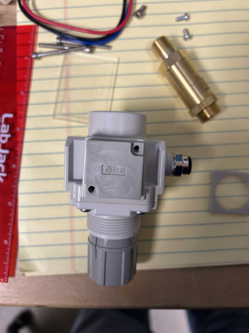 - install the dial on the side you took the plate off of, and the plate on the opposite side, using the screws you removed. Tighten screws snug, you will feel the rubber o-rings engaging on both sides.
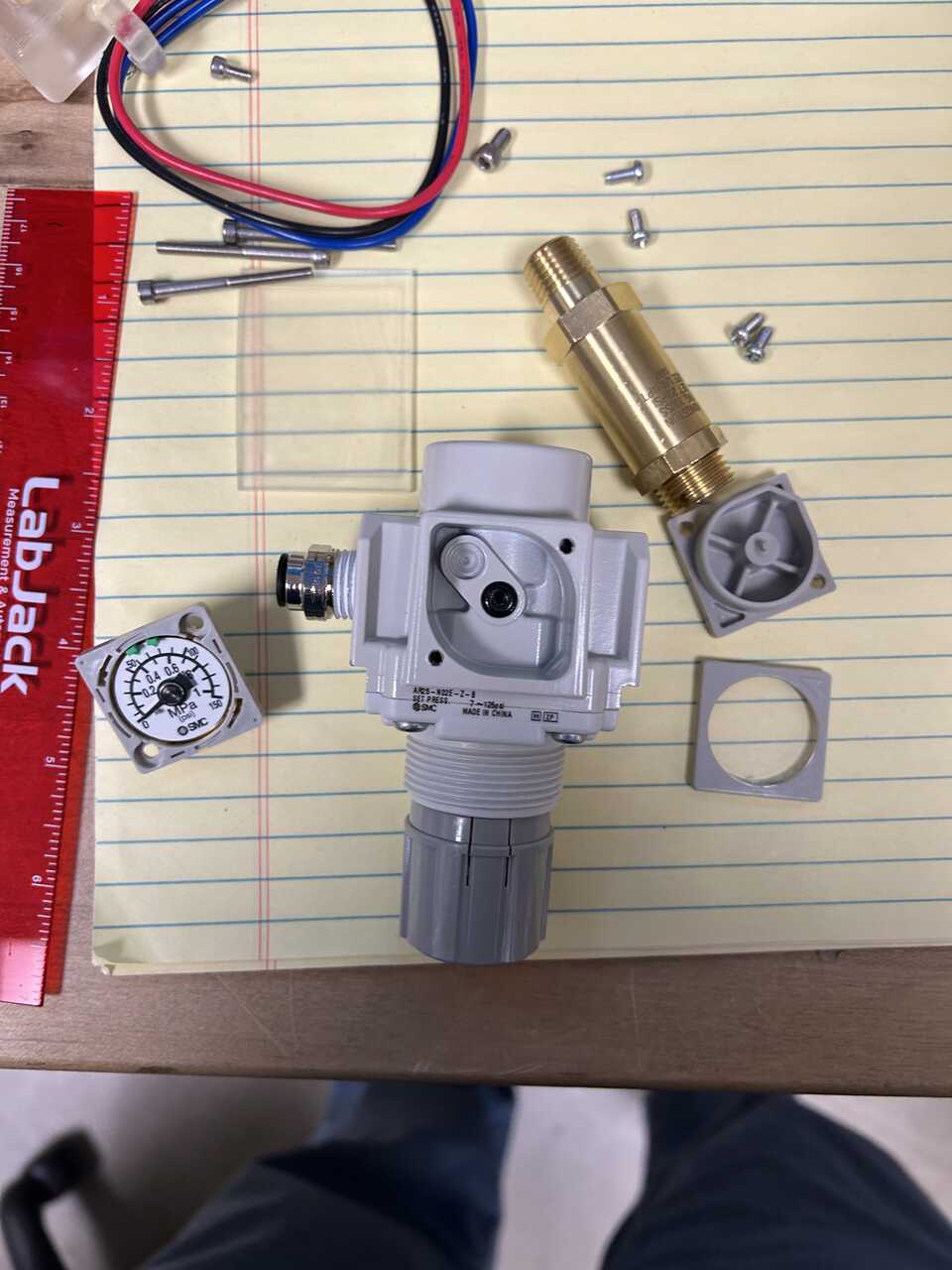
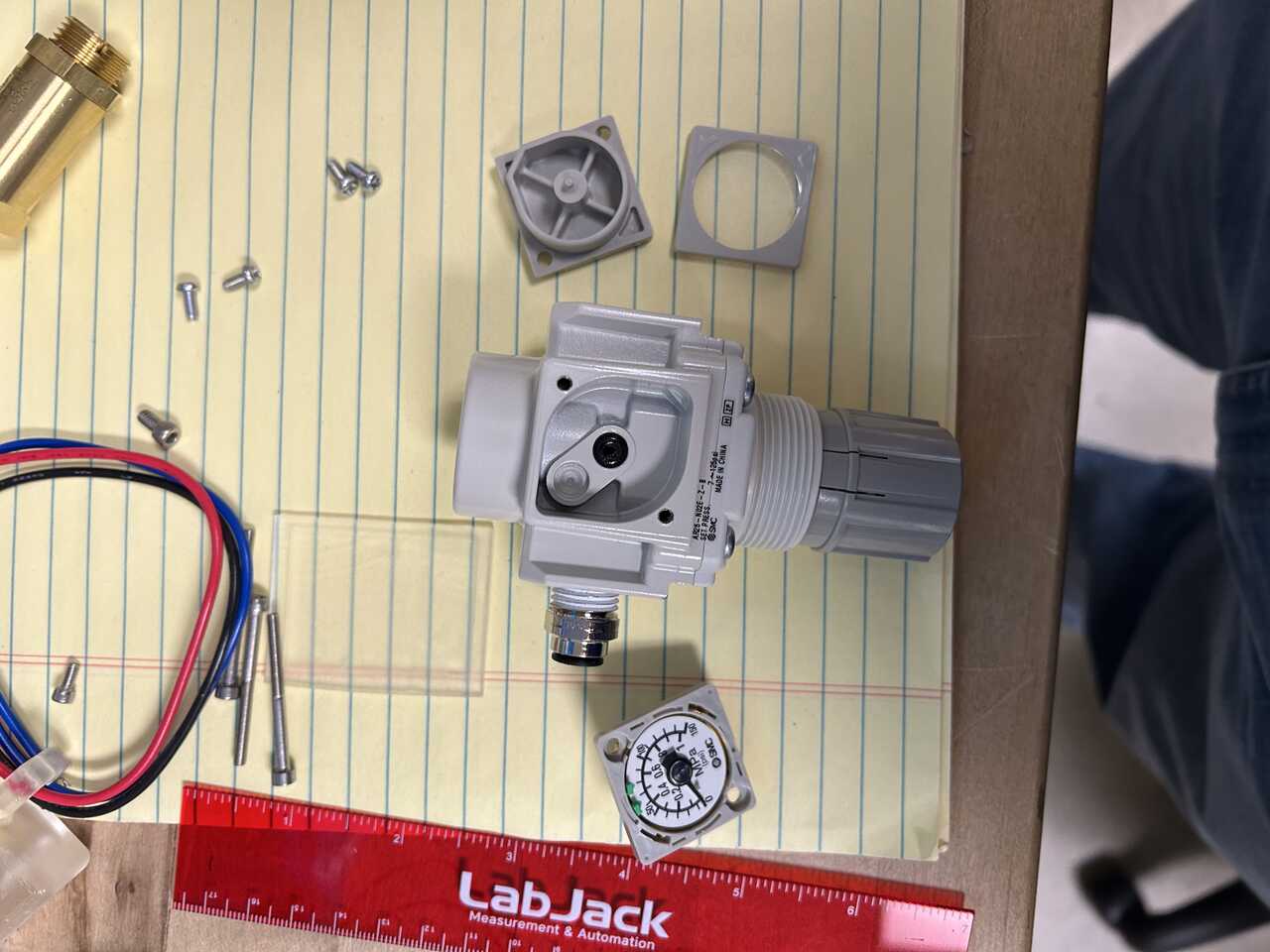
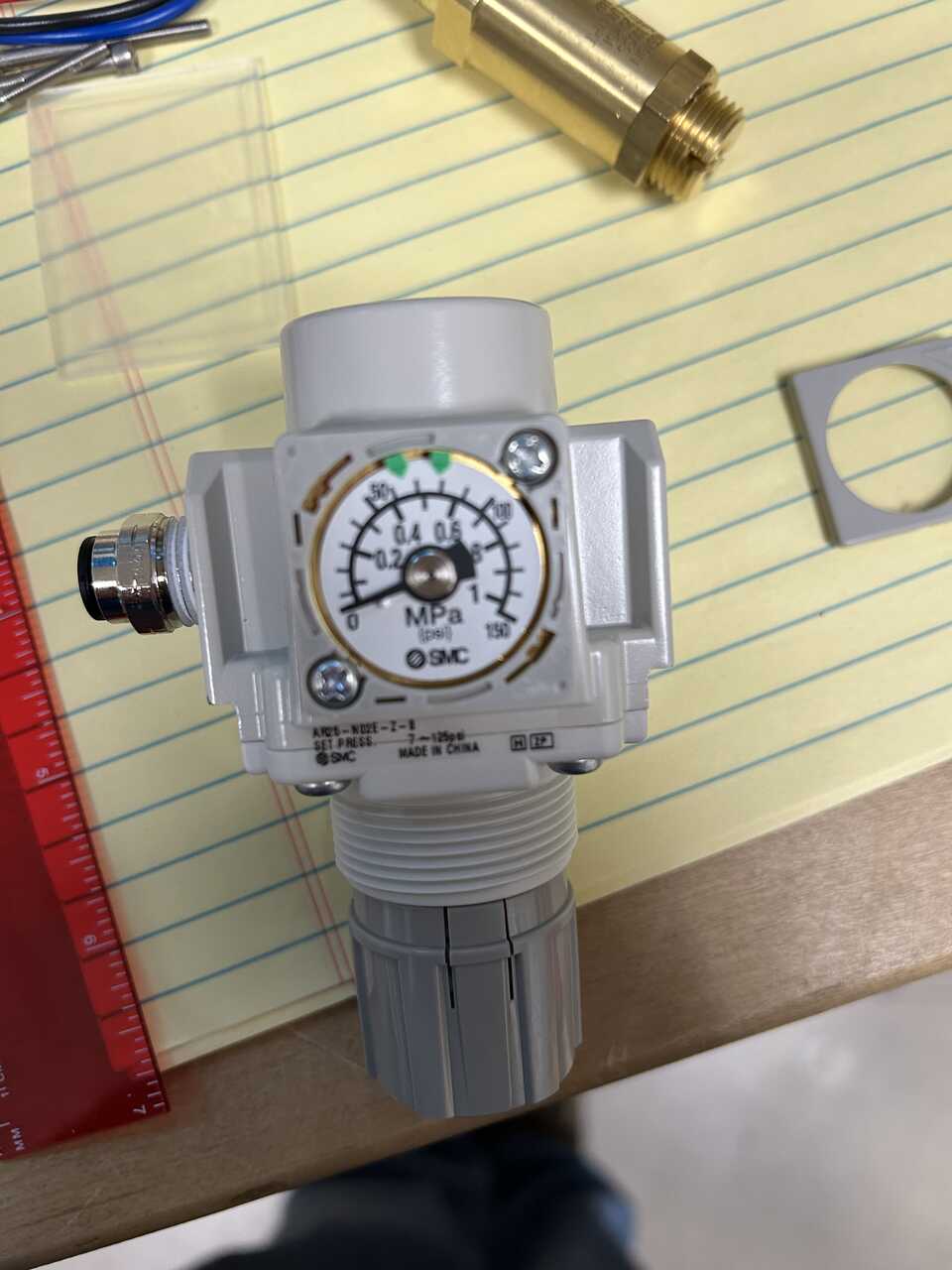
 - set the green arrows on the dial face to the pressure range for the regulator (10-20 psig for the dispense regulator, 40-80 psig for the actuator regulator). These are just a usability indicator.
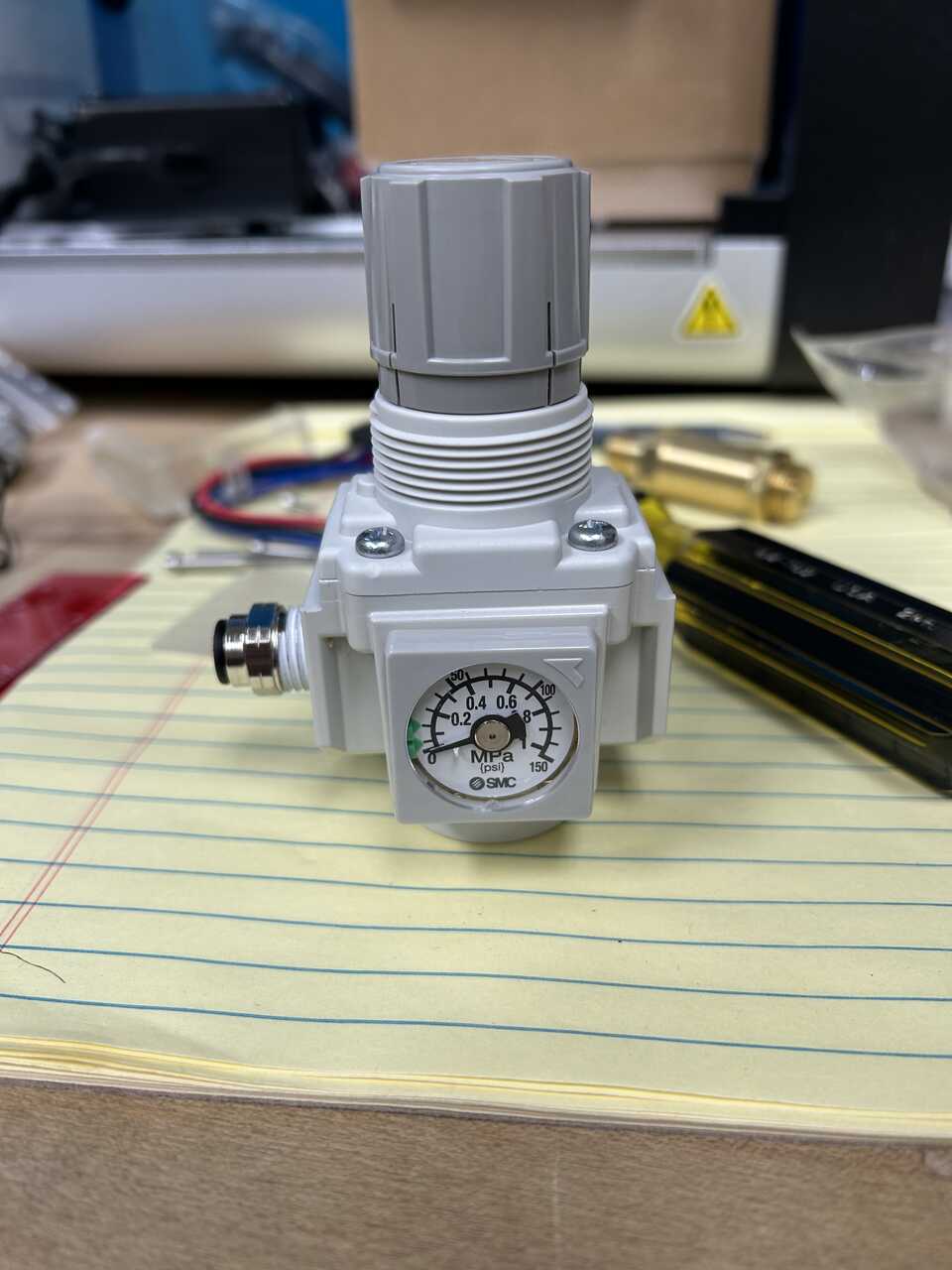
- replace the faceplate aligning the grooves and rotate to lock in place.
- you should now have a regulator that sits flat on the bottom, inlet on left, outlet on right.
- set the green arrows on the dial face to the pressure range for the regulator (10-20 psig for the dispense regulator, 40-80 psig for the actuator regulator). These are just a usability indicator.
- replace the faceplate aligning the grooves and rotate to lock in place.
- you should now have a regulator that sits flat on the bottom, inlet on left, outlet on right. -
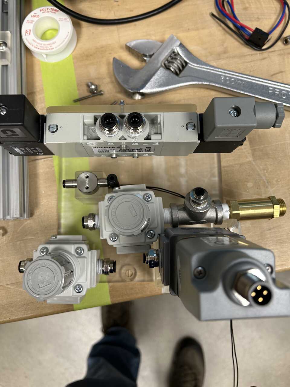
Mount the valve to the designated position on the frame using M3x35 screws, M3 nuts, and a 2.5mm hex wrench. The valve should be oriented matching the holes on the frame.
-
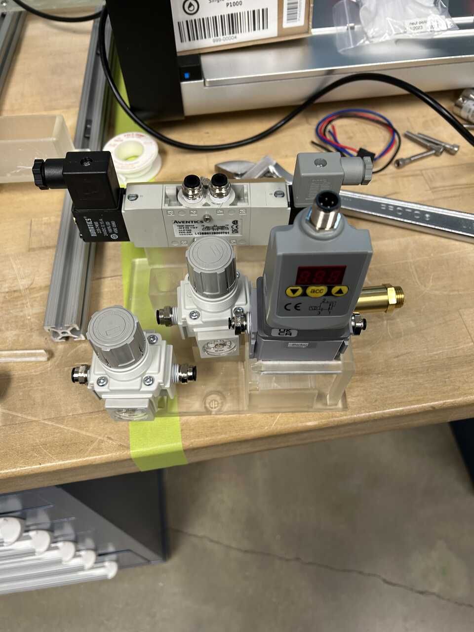
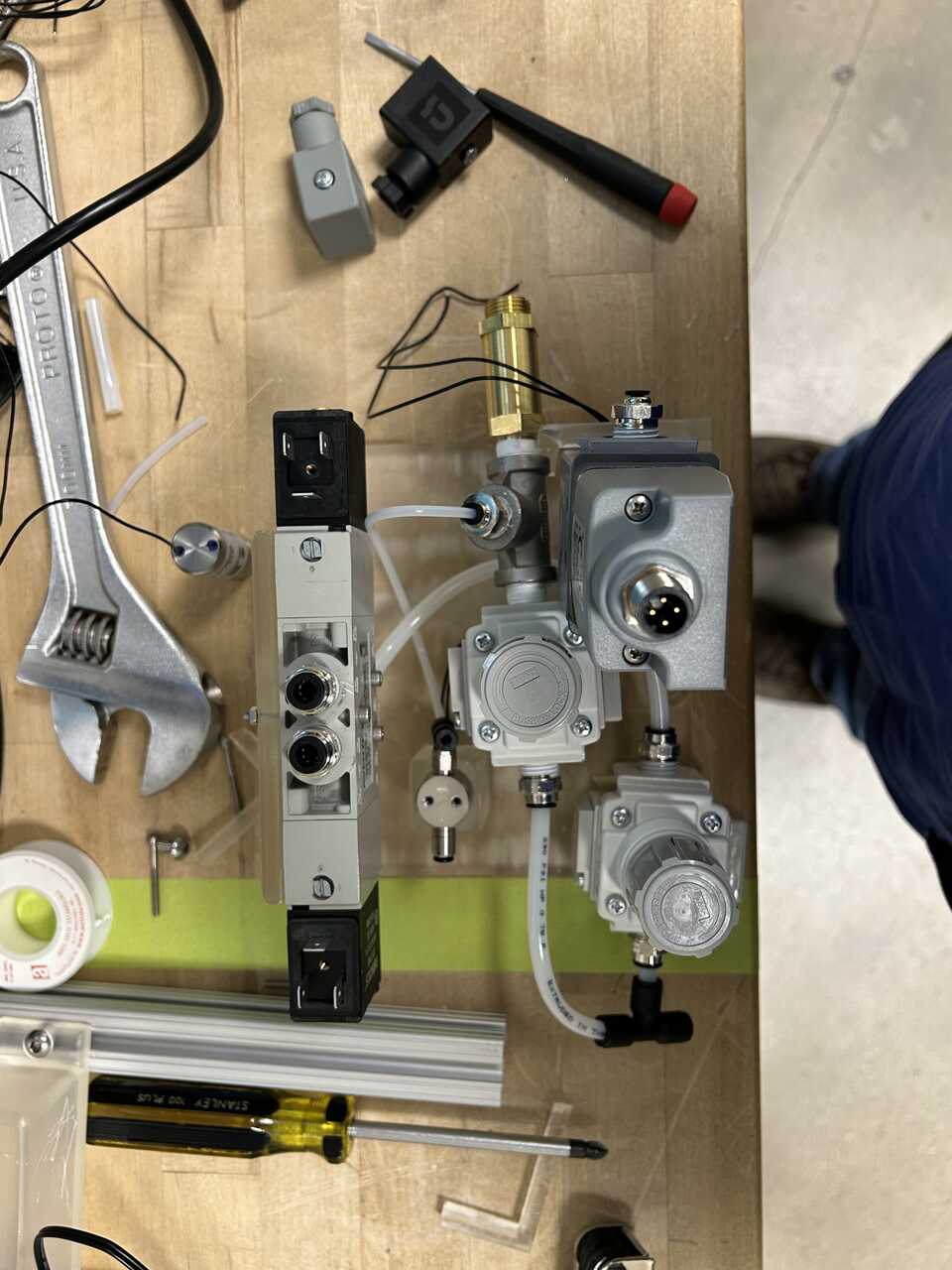
Place the two regulators in their designated positions on the frame. One regulator will be used for the actuator pressure (60-80 psig) and the other for the dispensing pressure (15-30 psig), actuator on left, dispense on right
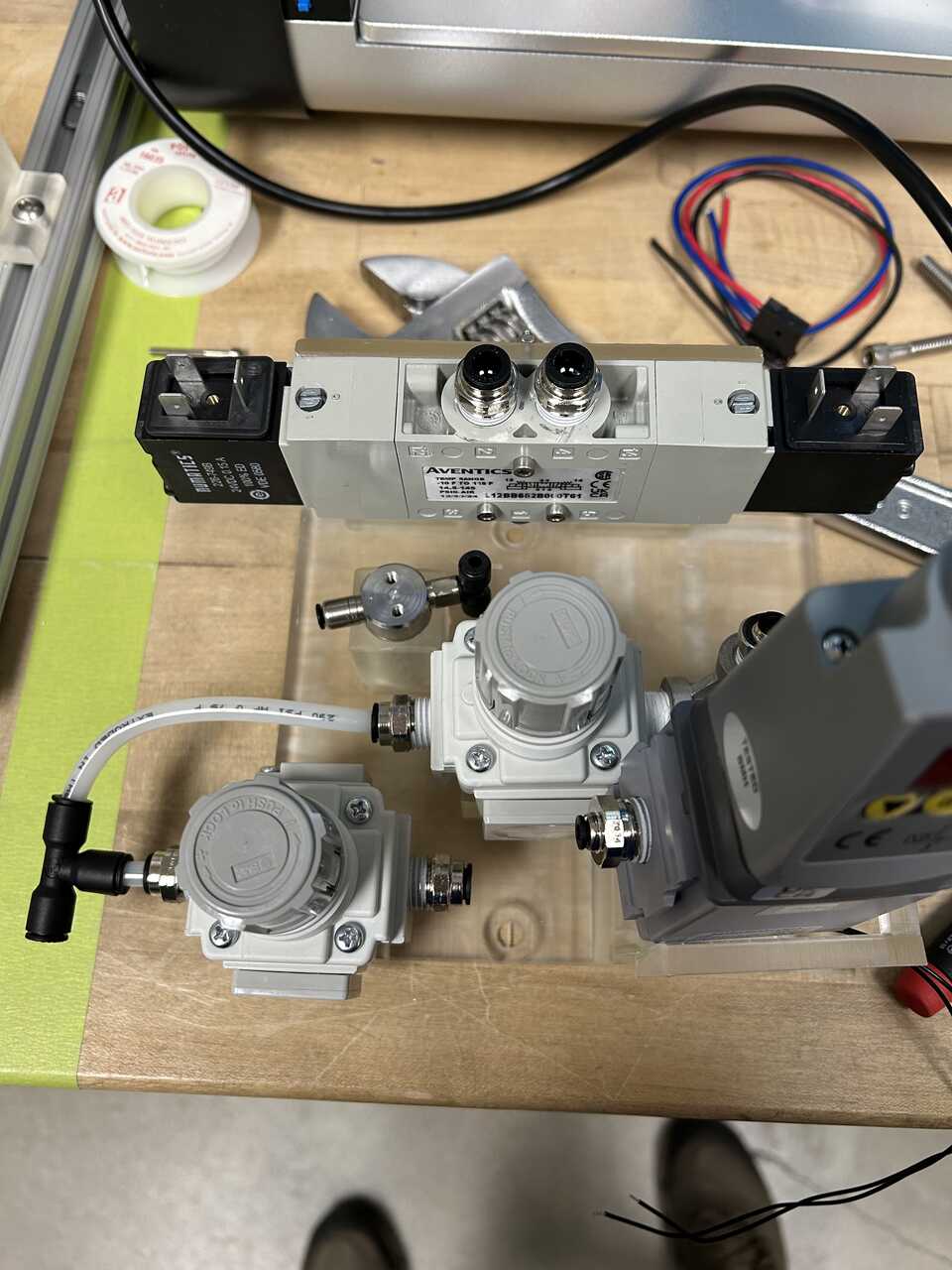
Step 2: Install pneumatic connections
- Place the fitting-equipped components into the slots on the frame. Thread the wires from the enable valve through the slot in the bottom of its housing and into the connection box at front right.
We will generally proceed in the order from inlet to outlet.
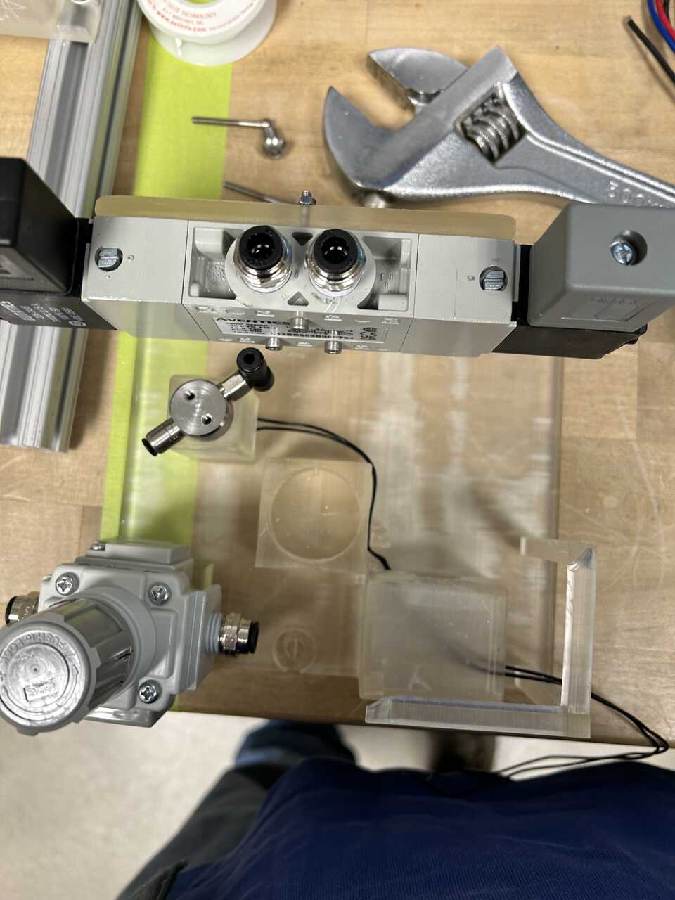
- Run a NylonTube14OD from either the tee on the inlet of the actuator regulator, or a separate 14NylonPushTee to the inlet of the dispense regulator. If using a separate tee, run a short stub of NylonTube14OD to connect the tee to the inlet of the actuator regulator - we found 32 mm sufficient for the insertion depth of two fittings.
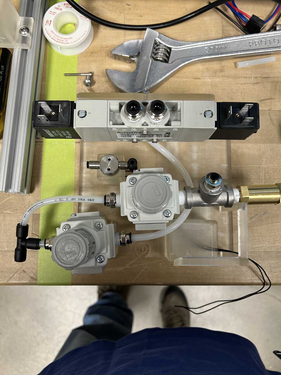
-
Connect the actuator regulator output to the input of the five-way valve - port #1 on the bottom using NylonTube14OD. It is easiest to make up the fitting at the regulator with excess tubing, run the line, and mark/cut the precise length to reach the valve. We're done with the first (actuator) system!
-
Next, we'll run a line from the dispense regulator output to the enable valve inlet tee (or a separate Nylon push connect tee). Connect some TefzelTube18OD to the tee, and run it to the enable valve tee on the bottom input.
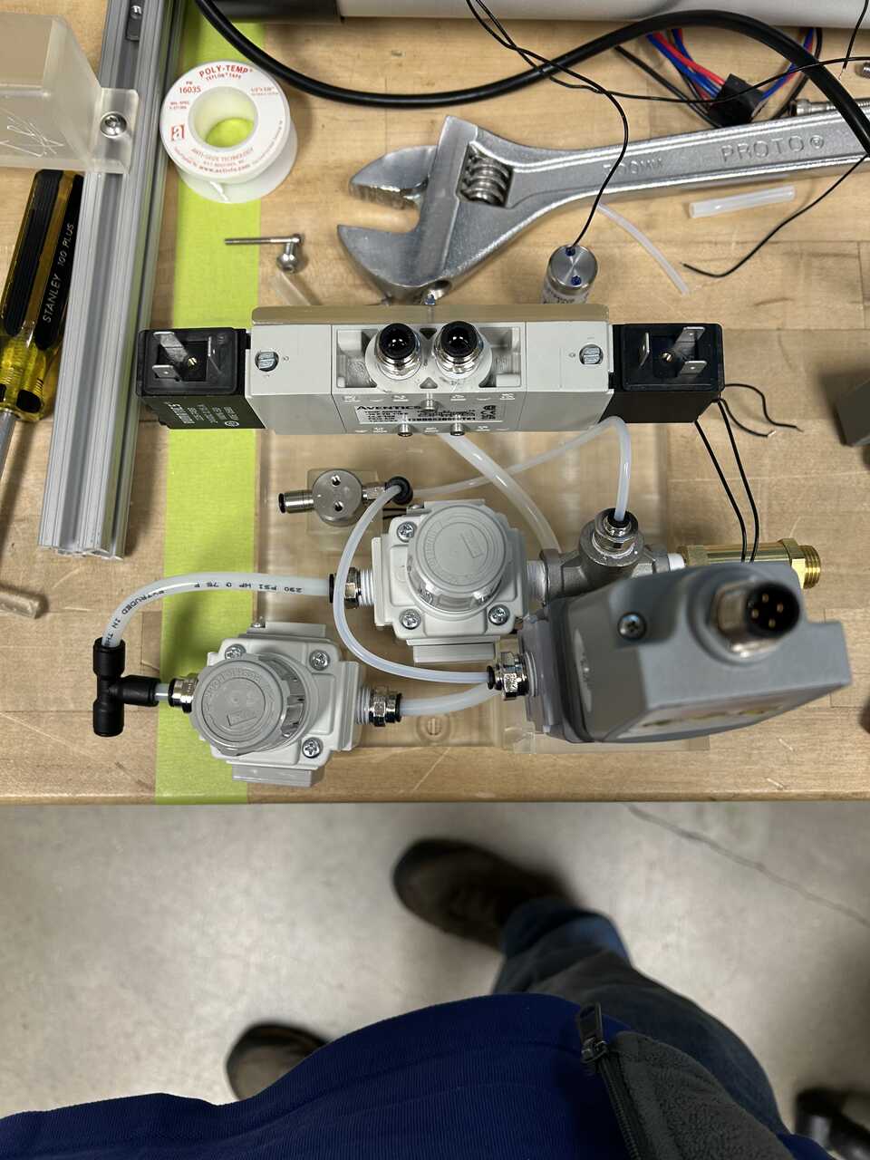
- Next, we'll run a line from the enable valve input to the dispense controller inlet. Connect some TefzelTube18OD to the tee, and run it to the left side of the dispense controller. Done with dispense!
We now have 4 exposed ports on the pneumatic controller: - two 1/4" push connect ports for the actuator up and down lines - a 1/8" push connect port for the controlled dispense - a 1/8" push connect port to the bottles and blowout valves
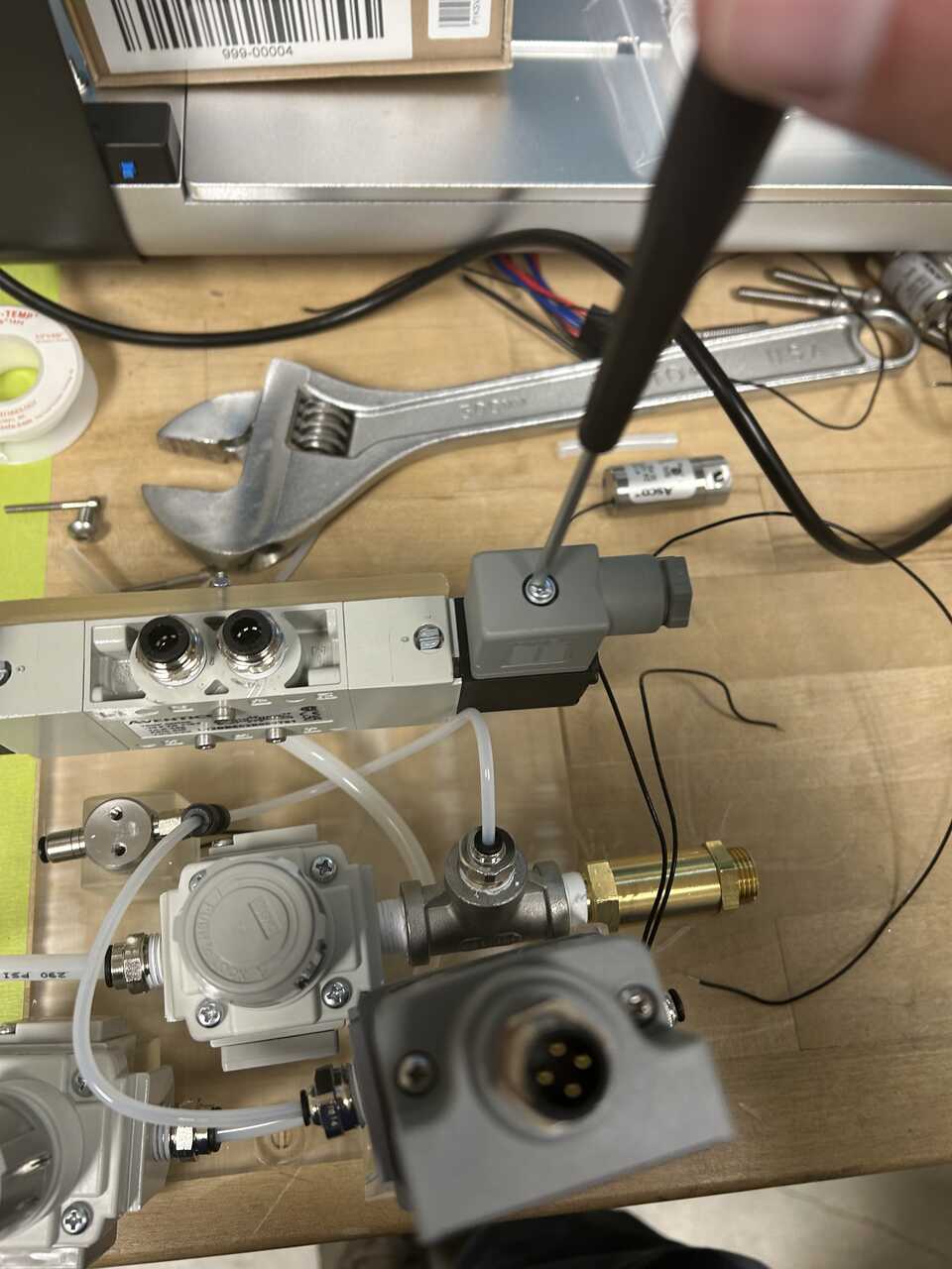
Step 3: Make up electrical connections
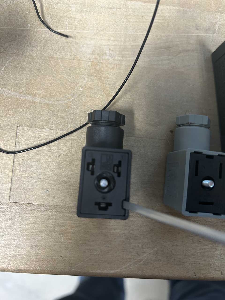
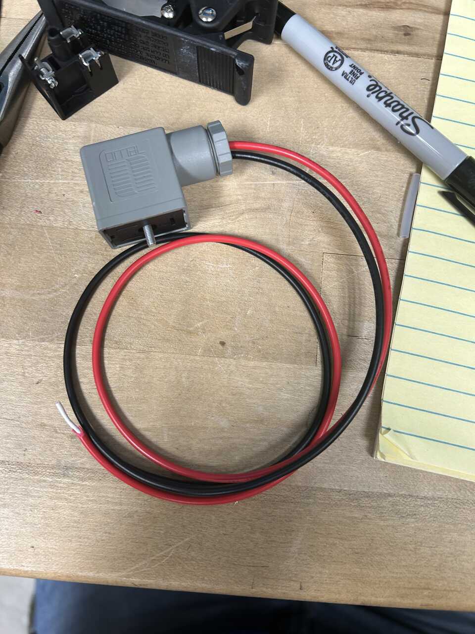
- Using a Phillips No. 2 screwdriver, remove the two connectors from the two sides of the five-way valve.
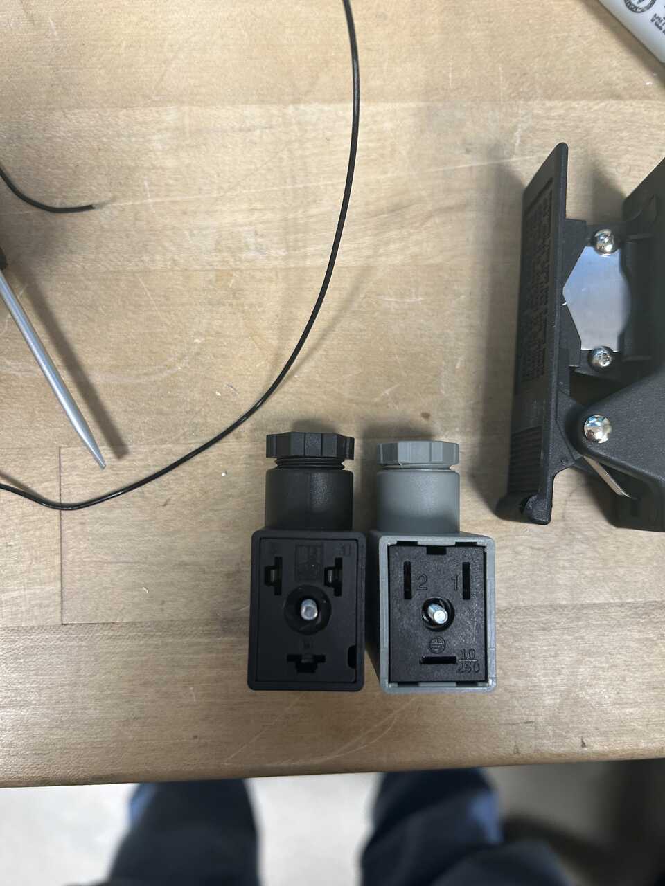
- It is helpful for space-saving reasons to flip the inner part of the connector so the wires face inward. To do so, insert a flathead screwdriver into the slot on the connector and pry the terminal block out, you may need to unscrew the top screw more to get past the captive section. When we reassemble these connectors, we will want to have the cable exit facing the ~single~ side of the connector rather than the double.
-
Get some hook-up wire; almost any two-conductor wire will do. We will be connecting the RJ45 jack to the control inputs of the five-way valve. It is helpful to have two colors or ideally three - up, down, and common. The conventions here are mostly a suggestion.
-
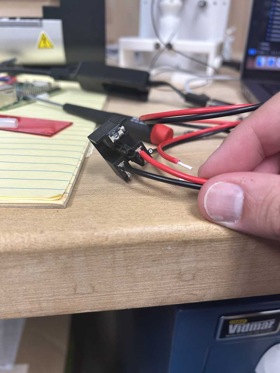
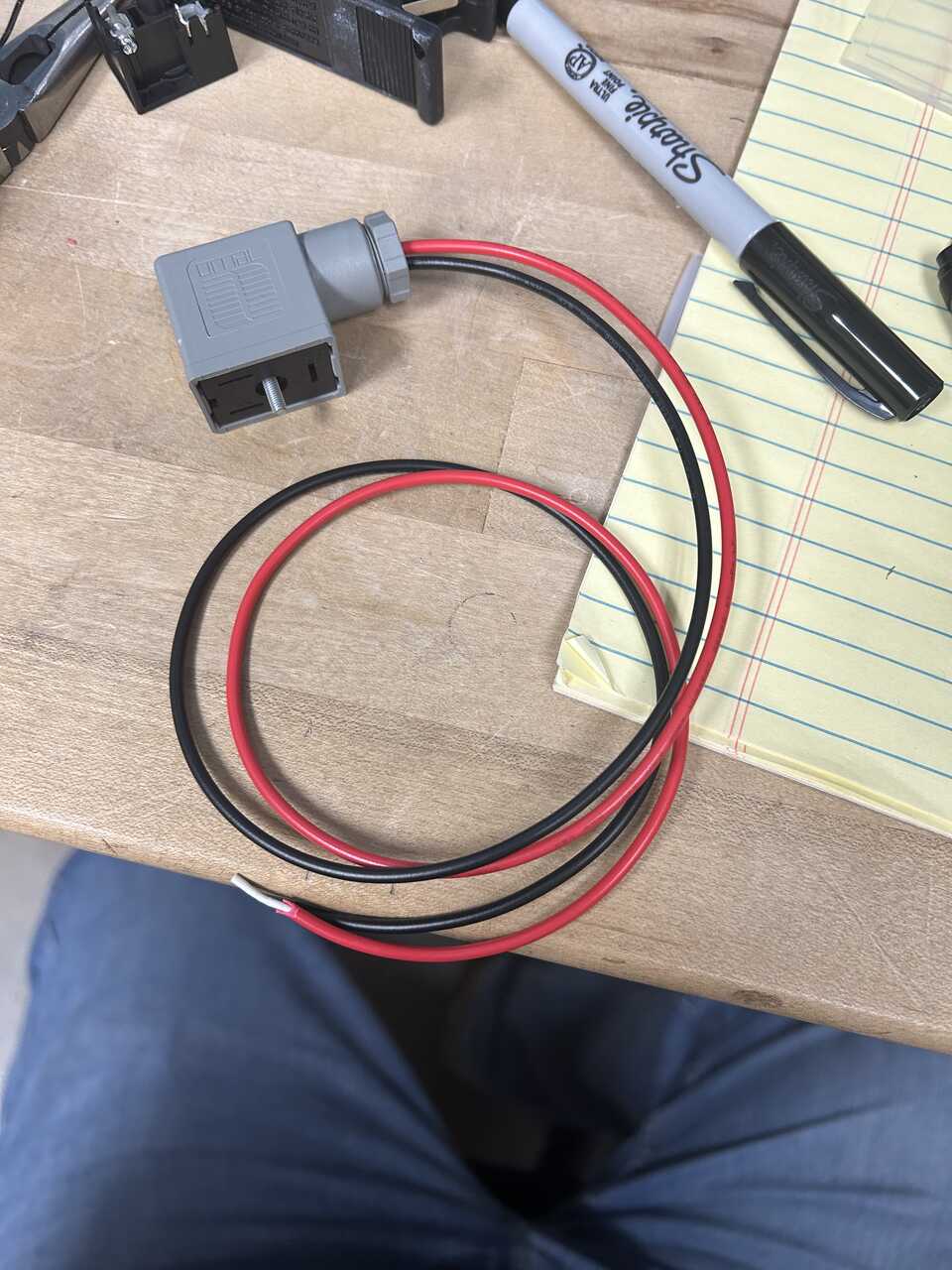
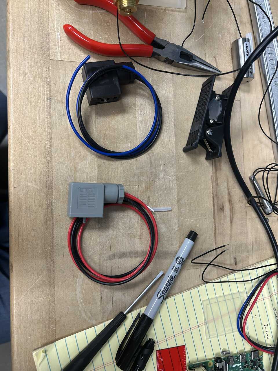
Connect the red line to the #1 terminal inside the beige connector and a black line to the #2 terminal. Run the wire through the strain relief and out. Re-seat the screw, tighten the strain relief, and snap the connector into place
-
Repeat for the blue line on the #1 terminal of the black connector.
-
Connect the plugs to the five-way valve and route the wires into the connector box.
- Land the wires on the RJ45 following the pinout:
| Pin | Color | Function |
|---|---|---|
| 1 | Red | Up |
| 2 | Black | Up-Common |
| 4 | Blue | Down |
| 5 | Black | Down-Common |
| 7 | Black (unlabeled) | Enable |
| 8 | Black (unlabeled) | Enable-Common |
- Place the RJ45 in position and neatly store the excess wire in the box.
Step 4: Test the pneumatic system
-
Before connecting to the robot, test the pneumatic system for leaks by applying pressure and using soapy water to check all connections.
-
Verify that the regulators can be adjusted to the required pressure ranges:
- Actuator regulator: 60-80 psig
-
Dispensing regulator: 15-30 psig
-
Test the operation of the five-way valve by applying control signals through the RJ45 connection.
-
Ensure that all safety features, including pressure relief valves, are functioning correctly.
Step 5: Connect to the robot system
-
Once testing is complete, the pneumatic module is ready to be connected to the robot system.
-
Connect the actuator line to the in-robot module using the appropriate tubing and connectors.
-
Connect the dispensing lines to their respective components.
-
Connect the RJ45 cable from the pneumatic module to the electronics module to enable control of the pneumatic system.